Privacy statement: Your privacy is very important to Us. Our company promises not to disclose your personal information to any external company with out your explicit permission.
Select Language
The welding experiment and production practice prove that: when welding, when argon gas flows out from the nozzle, a protective hood is formed in the nozzle and the welding zone to deliver air in advance; when the arc is triggered, the high frequency passes through the gap between the electrode and the iron core to ignite the air ionization. Arc; arc heat causes the weld to melt and form a heat-affected zone; since the iron core is pure iron or silicon steel sheet, the heat transfer capacity is greater than that of air, so the iron core is heated in the direction of the arrow to cause the tooth to expand; when cooling, due to the molten pool It is exposed to the air, so the cooling is fast, the core is shrunk inward, and the protrusion is caused by the pressure of the clamp to expand into the inner hole of the tooth core and the groove thereof. At the same time, after the Stator Core is cooled, the requirements of verticality and flatness are not achieved.
When the wire is embedded, the stator core has a protruding piece, which is easy to cause the winding to break down to the ground, which makes the product unqualified. Therefore, the bead design is not suitable on the center line of the stator core yoke portion.
2.2.4 Correct design of weld bead position
1 outer edge is a square stator
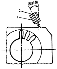
The bead design should be away from the slots and teeth of the stator core, as shown in Figure 2. When welding, the groove and the tooth portion of the iron core are away from the heat-affected zone, and are not affected by or less affected by the heat of welding, thereby reducing thermal deformation.

1. Nozzle 2. Tungsten electrode
Figure 2 Schematic diagram of the weld bead away from the groove
2 The outer edge is a circular stator
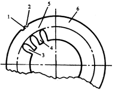
The bead design can be designed as shown in Figure 3, which is designed on the center line of the yoke of the stator slot to facilitate heat conduction to the periphery and reduce post-weld deformation.

1. Bump 2. Bead groove 3. Slot 4. Tooth 5. Yoke 6. Iron chip
Figure 3 Schematic diagram of the correct design of the weld bead
The weld bead should be designed as a grooved weld bead and designed with bumps in the groove (see Figure 3). This design not only enhances the protection of argon, but also because the bump is higher than the groove on both sides, the heating volume is small, and the heat is small. The melting amount is small, the heat affected zone is small, the welding current can be correspondingly reduced, and the welding time can be appropriately shortened. Therefore, the deformation of the stator core after welding is small, and the inner hole of the stator core does not need to be processed, thereby avoiding the defects existing in the original design. At this time, the design of the product is designed to meet the reliability design of argon arc welding.
3 argon arc welding process design reliability
3.1 argon arc welding of the stator by a single argon arc welding machine
When using hand arc welding, the straightness of the weld is poor, and the special running track is designed. The weld can meet the straightness requirement, but the clamping takes time and labor, the stator is heated and cooled unevenly, the thermal deformation is large, and it is inevitable The gap size is inconsistent. Therefore, the flatness and the inner hole size of the stator core are difficult to ensure, and the inner hole must be ground by an internal grinding machine to ensure the matching air gap between the stator and the Motor Rotor. Therefore this method is also not advisable.
To this end, after collecting a large amount of information analysis and processing at home and abroad, the design process of the multi-pass weld joint welding of the stator core by the DYH-200 welding unit of the Sanliang four-column welding machine was studied.
Previous Next
April 10, 2023
September 22, 2022
March 17, 2022
April 21, 2023
April 19, 2023
May 13, 2023
May 03, 2023
Through years of technical research and development and practical experience, Yongrong Power Co., Ltd. has developed a new set of cast aluminum manufacturing process, making its products in strength,...
The rotor with shaft is a kind of widely developed and adopted motor design, also known as the magnetic pump rotor, compared with the ordinary motor, it adopts different design concept of the...
Progressive punching is an efficient self-riveting process of fixed rotor, which can realize large-scale and precise riveting operation and is suitable for mass manufacturing production line. The...
Laser cutting provides greater precision in stator and rotor machining, using a highly focused beam that acts as a heat-affected zone during cutting without causing extensive thermal damage to...
Email to this supplier
April 10, 2023
September 22, 2022
March 17, 2022
April 21, 2023
April 19, 2023
May 13, 2023
May 03, 2023

Privacy statement: Your privacy is very important to Us. Our company promises not to disclose your personal information to any external company with out your explicit permission.

Fill in more information so that we can get in touch with you faster
Privacy statement: Your privacy is very important to Us. Our company promises not to disclose your personal information to any external company with out your explicit permission.