


Please Leave Us A Message
Privacy statement: Your privacy is very important to Us. Our company promises not to disclose your personal information to any external company with out your explicit permission.
Select Language

Abstract: This paper first discusses the stability design of the stator-core superpose. Then it concludes that the good inherent reliability of a product is determined by its overall design, process design and inter-process design of the product.
Keywords: stator-core superpose overall design process design inter-process design
1 Overview
Motor Stator Core stacking, people often think that its reliability design is done by the motor designer, as long as the iron core design, the stator core stacking diagram and the necessary technical conditions, its reliability design has been Completed; or considered that the stator core stacking is purely in the manufacturing scope, as long as the reliability of the process design is good. However, the stator core is a key component in the motor and affects the function of the complete machine. Its inherent reliability is the reliability that has been identified and ultimately achieved on the product during the design and manufacturing process and can be described by:
R=R . R
Where R I - the inherent reliability of the product;
R D - the potential reliability imparted to the product during the design process;
R m - Manufacturing reliability determined by engineering capabilities resulting from the manufacturing process.
It can be seen from the above formula that the product must obtain good inherent reliability, and the design link and the manufacturing process must be closely coordinated. Because each process has a product design, process design and process design problems before the process, so the above two The views are not comprehensive. This article only discusses some of these issues.
2 stator core forming design
The stator core stack design can be chosen in different manufacturing methods. The following examples illustrate several methods for feasibility and reliability analysis.
2.1 Stacking buckle or riveting of stator core
After the stator core is stacked, the traditional design is to design a buckle groove on the iron chip, which is fastened with a buckle. When the stack thickness exceeds 40 mm, in order to ensure the stator stacking strength and avoid deformation, the rivet holes should be designed on the holes instead of the grooves, and the rivets are riveted. After the two methods are processed, the verticality, the flatness of the end face, the inner hole of the iron core, the shape of the wire groove often fail to meet the design requirements, the inner hole must be ground, the iron chips are easy to overlap each other, and the motor is added. Defect. Therefore, this design has not adapted to the needs of the development of motor technology.
2.2 Stator core argon arc welding design
2.2.1 The weld bead is designed on the surface of the outer edge of the stator core
This design, when argon arc welding, the heating volume is large, the thermal deformation is large, the weld bead distribution is not uniform, and the individual parts are sometimes higher than the outer edge of the iron core. When it is pressed into the motor casing, the inner and outer circles need to be processed. Therefore, this design is poor in reliability.
2.2.2 Designing the bead groove on the outer edge of the stator core
For this design, the protection of argon and the concentration of heating can be improved during welding. After welding, the outer edge is not processed, but the thermal deformation is still large, and the inner hole must be processed, so it is not preferable.
2.2.3 Feasibility analysis of bead design on the center line of the stator core yoke
The weld bead is designed in the yoke of the tooth. The designer considers that the volume of the welded part is the sum of the volume of the tooth and the volume of the yoke. The conduction of heat is mainly conducted along a straight line, so the heat capacity is large, and the thermal deformation will change after welding and heating. small. Its design is shown in Figure 1.
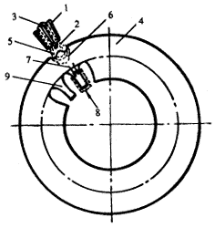
1. Nozzle 2. Air hood 3. Tungsten electrode 4. Iron yoke 5. Molten pool
6. Thermal shadow zone 7. Heat conduction direction 8. Tab 9. Tooth
Figure 1 Schematic diagram of the weld bead at the center of the yoke of the tooth
Next page

April 10, 2023

September 22, 2022

March 17, 2022
April 21, 2023
April 19, 2023
May 13, 2023
May 03, 2023
Through years of technical research and development and practical experience, Yongrong Power Co., Ltd. has developed a new set of cast aluminum manufacturing process, making its products in strength,...
The rotor with shaft is a kind of widely developed and adopted motor design, also known as the magnetic pump rotor, compared with the ordinary motor, it adopts different design concept of the...
Progressive punching is an efficient self-riveting process of fixed rotor, which can realize large-scale and precise riveting operation and is suitable for mass manufacturing production line. The...
Laser cutting provides greater precision in stator and rotor machining, using a highly focused beam that acts as a heat-affected zone during cutting without causing extensive thermal damage to...
Email to this supplier
April 10, 2023
September 22, 2022
March 17, 2022
April 21, 2023
April 19, 2023
May 13, 2023
May 03, 2023
About Us
Related Products List
Contact Us

Privacy statement: Your privacy is very important to Us. Our company promises not to disclose your personal information to any external company with out your explicit permission.
Fill in more information so that we can get in touch with you faster
Privacy statement: Your privacy is very important to Us. Our company promises not to disclose your personal information to any external company with out your explicit permission.